SPI (SERIAL PERIPHERAL INTERFACE)
INTRODUCTION:
The SPI is a very simply Synchronous (allows devices to send and receive data at the same time) protocol developed by Motorola. It is found on many devices and like I2C can be used to chain many devices together. The SPI protocol can simply be implemented in software however, the AVR has hardware SPI capability.
HARDWARE:
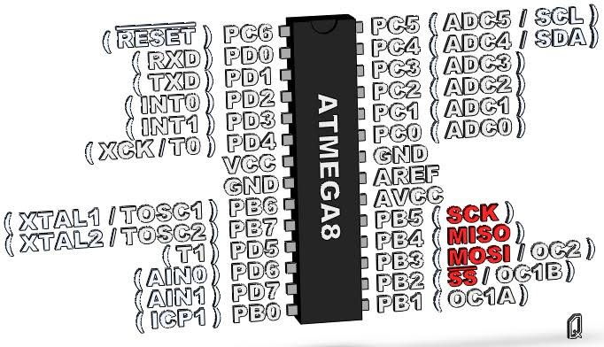
Figure 1: SPI Pinouts
SPI uses 4 pins, A system clock (SCK), a Master Output Slave Input (MOSI), a Master Input Slave Output (MISO) and a Slave Select (SS). These pins have many other commonly used names:
| NAME | ALTERNATE NAMES |
|---|---|
| SCK | CLK |
| MISO | SOMI, SDO, DO, SO |
| MOSI | SIMO, SDI, DI, SI |
| SS | CS, CSB, CSN, STE |
Table 1: Alternate SPI pin names
Because each slave device needs a dedicated SS line, you require 3 + #_of_Slave_Devices pins in order to operate a multi slave buss.
No additional hardware is required in order to run the SPI, no pullup resistors (like I2C), no end cap resistors, and no capacitors.
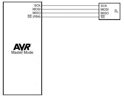
Figure 2: Single Slave
Note one thing, if you use a single slave, you could save yourself a pin by hooking up the SS pin on the slave to GND and the SS on the master to VCC.
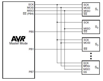
Figure 3: Multiple Slaves
THEORY OF OPERATION:
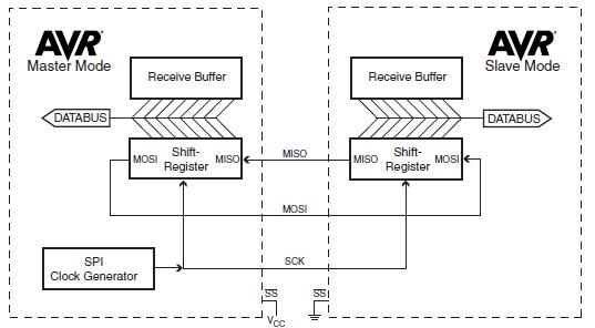
Figure 4: SPI Communication Block Diagram
The master generates the clock for the entire system and, is responsible for choosing which slave it wants to talk to. Setting the CS line LOW(GND) for the selected device will select it as the source device. The clock speed should be set to less than or equal to maximum speed of the slowest slave on your buss. When the clock pulses the Slave will read the state of the MOSI pin and the Master will read the state of the MISO pin. The AVR uses an 8 bit shift register, this means that after 8 pulses of the clock the 8 bit Master and Slave have both exchanged a bite of data.
Shift Register:
The previously mentioned shift register is a bit crazy. Let's say we are transmitting from the Master to the Slave. Each clock cycle the register will be shifted to the left by one in both the Master and the Slave. The most significant bit (MSB or 7 bit) of the Master will be pushed to the least significant bit (LSB or 0 bit) of the Slave (MOSI line on Figure 4) and, the Slaves MSB will be pushed to the Masters LSB (MISO line on Figure 4). So after 8 of these exchanges the contents of both registers will be exchanged with each other.
Clock Polarity and Clock Phase:
It can't be as simple as setting the clock speed can it? Well you'r right. We also have to set up the SPI mode. The mode consists of 2 settings the Clock Polarity and Clock Phase:
| Mode | CPOL | CPHA |
|---|---|---|
| 0 | 0 | 0 |
| 1 | 0 | 1 |
| 2 | 1 | 0 |
| 3 | 1 | 1 |
Table 2: SPI Modes
So, what do these modes mean?
The Clock Polarity decides what whether the data is sent on rising edge or the falling edge. If CPOL is set to LOW(0) data is sent/received on the Rising Edge and the status of the pins updated(for the next read) on the Falling Edge. If CPOL is set to HIGH(1) data is sent/received on the Falling Edge and the status of the pins is updated(for the next read) on the Rising Edge.
The Clock Phase decides when to read the data. If CPHA is set to LOW(0) data will be reed on the leading edge of the clock. If CPHA is set to HIGH(1) data will be reed on the trailing edge of the clock.
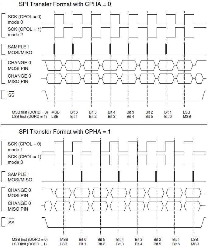
Figure 5: SPI Timing Diagram
| 7 bit | 6 bit | 5 bit | 4 bit | 3 bit | 2 bit | 1 bit | 0 bit | |
|---|---|---|---|---|---|---|---|---|
| SPCR | SPIE | SPE | DORD | MSTR | CPOL | CPHA | SPR1 | SPR0 |
SPI Control Register
| Mode | CPOL | CPHA |
|---|---|---|
| 0 | 0 | 0 |
| 1 | 0 | 1 |
| 2 | 1 | 0 |
| 3 | 1 | 1 |
Table 2: SPI Modes
| 7 bit | 6 bit | 5 bit | 4 bit | 3 bit | 2 bit | 1 bit | 0 bit | |
|---|---|---|---|---|---|---|---|---|
| SPSR | SPIF | WCOL | - | - | - | - | - | SPI2X |
SPI Status Register
| SPI2X | SPR1 | SPR0 | SCK Frequency |
|---|---|---|---|
| 0 | 0 | 0 | Clock / 4 |
| 0 | 0 | 1 | Clock / 16 |
| 1 | 0 | 0 | Clock / 64 |
| 0 | 1 | 1 | Clock / 128 |
| 1 | 0 | 0 | Clock / 2 |
| 1 | 0 | 1 | Clock / 8 |
| 1 | 1 | 0 | Clock / 32 |
| 1 | 1 | 1 | Clock / 64 |
System Clock Division Factor
| 7 bit | 6 bit | 5 bit | 4 bit | 3 bit | 2 bit | 1 bit | 0 bit | |
|---|---|---|---|---|---|---|---|---|
| SPDR | MSB | LSB |
SPI Data Register
Setting the SPE bit within the SPCR register enables SPI.
Setting the SPIE bit HIGH (1) enables the SPI interrupt.
The DORD bit within the SPCR register controls the direction of the transmission. The default is LOW(0) will transmits MSB first and LSB last, if the bit is SET(1) will transmit the LSB first and the MSB last.
The MSTR bit within the SPCR register tells the AVR whether it is a master or a slave. If the SS pin is set as an input while the AVR is in Master Mode and, the pin is driven LOW (GND), the MSTR bit will be cleared (0) and the user must set the bit HIGH(1) to re-establish Master mode.
The SPIF bit within the SPSR sets HIGH(1) whenever data transmission is complete even if interrupts are not enabled. This is useful because we could check the status of the bit in order to figure out if it is safe to write the SPDR register.
Writing to the SPDR register causes data to be loaded into the shift register and automatically triggers the AVR to transmit. Reading from the SPDR register causes the data to be read from the reception shift register.
The WCOL bit within the SPSR register will be set HIGH(1) if you attempt to write data into the SPDR register during data transmission. WCOL will be cleared (0) when the SPDR is reed.
SOFTWARE:
It's not very often when the ATmega8 and ATmega168/328 use the same registers, but guess what the SPI is the same. I love it because it saves me from writing another tutorial.
ATmega8 & ATmega168/328 Code:
    // this program enables SPI communication and
    // Sets the AVR into Master mode

    #include <avr/io.h>

    int main (void)
    {
        char data;

        DDRB |= (1 << 2) | (1 << 3) | (1 << 5);    // SCK, MOSI and SS as outputs
        DDRB &= ~(1 << 4);                         // MISO as input

        SPCR |= (1 << MSTR);                 // Set as Master
        SPCR |= (1 << SPR0) | (1 << SPR1);   // divided clock by 128
        SPCR |= (1 << SPE);                  // Enable SPI

        while(1)
        {
            SPDR = data;                   // send the data
            while(!(SPSR & (1 << SPIF)));  // wait until transmission is complete

            // if you have multiple slaves, this is where you want to switch
        }
    }
Now I shall use my captain obvious powers to say, both of these programs can be used to communicate with each other.
ATmega8 & ATmega168/328 Code:
    // this program enables SPI communication and
    // Sets the AVR into Slave mode

    #include <avr/io.h>

    int main (void)
    {
        char data;

        DDRB &= ~((1 << 2) | (1 << 3) | (1 << 5));   // SCK, MOSI and SS as inputs
        DDRB |= (1 << 4);                            // MISO as output

        SPCR &= ~(1 << MSTR);                    // Set as slave
        SPCR |= (1 << SPR0) | (1 << SPR1);       // divide clock by 128
        SPCR |= (1 << SPE);                      // Enable SPI

        while(1)
        {
            while(!(SPSR & (1 << SPIF)));    // wait until all data is received
            data = SPDR;                     // hurray, we now have our data
        }
    }
Alternately, we could do the same BUT with using interrupts.
ATmega8 & ATmega168/328 Code:
    // this program enables SPI communication and
    // Sets the AVR into Master mode using interrupts

    #include <avr/io.h>
    #include <avr/interrupt.h>

    volatile data;

    int main (void)
    {
        char blah;

        DDRB |= (1 << 2) | (1 << 3) | (1 << 5);    // SCK, MOSI and SS as outputs
        DDRB &= ~(1 << 4);                         // MISO as input

        SPCR |= (1 << MSTR);                   // Set as Master
        SPCR |= (1 << SPR0) | (1 << SPR1);     // divided clock by 128
        SPCR |= (1 << SPIE);                   // Enable SPI  Interrupt
        SPCR |= (1 << SPE);                    // Enable SPI

        sei();

        while(1)
        {
            if ((SPSR & (1 << SPIF)) > 0)  // checks to see if the SPI bit is clear
                data=blah;                 // send the data

            // if you use multiple slaves, switch slave here.
        }
    }


    ISR (SPI_STC_vect)
    {
        SPDR = data;
    }
ATmega8 & ATmega168/328 Code:
    // this program enables SPI communication and
    // Sets the AVR into Slave mode

    #include <avr/io.h>
    #include <avr/interrupt.h>

    volatile data;

    int main (void)
    {
        DDRB &= ~((1 << 2) | (1 << 3) | (1 << 5));   // SCK, MOSI and SS as inputs
        DDRB |= (1 << 4);                            // MISO as output

        SPCR &= ~(1 << MSTR);                    // Set as slave
        SPCR |= (1 << SPR0) | (1 << SPR1);       // divide clock by 128
        SPCR |= (1 << SPIE);                     // Enable SPI  Interrupt
        SPCR |= (1 << SPE);                      // Enable SPI

        sei();

        while(1)
        {
            ;
        }
    }

    ISR (SPI_STC_vect)
    {
        data = SPDR;
        // do something with the received data
    }
OTHER RESOURCES:
Woot, all the episodes of Angel are now on Netflix I love Darla (Julie M. Benz). Google it, I can't do everything for you.
Cheers
Q