PWM ON THE ATmega8
INTRODUCTION:
We know that the AVR lets us turn outputs on and off, but, what if we want to control the brightness of an LED or the speed of a motor? Well the easiest way to do this is to change the voltage of the output, but we can fake it. If we take a voltage source and connect it for a second and then disconnect it for a second it will... well be on for a second then off for a second. BUT, if we manage to speed this up so that we connect/disconnect the power supply over 1000 times a second we can fool the power supply into thinking that our signal is half the value of the power supply. This is called Pulse Width Modulation or PWM for short.
THEORY OF OPERATION:
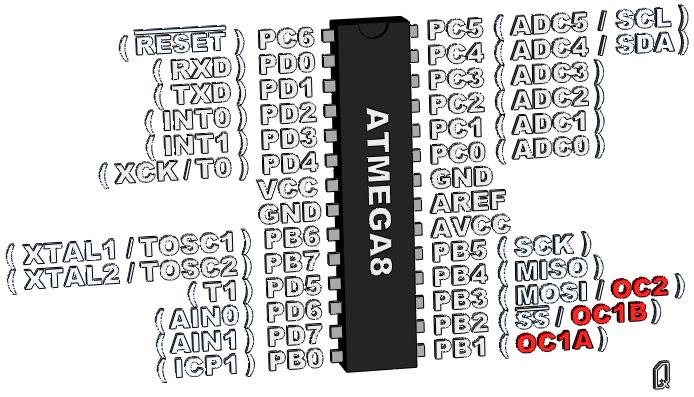
Figure 1: ATmega8 - PWM Pins
When you take a square wave, its on for a while and off for a while. If we divide the on by the off and multiply by 100% we will get what is called a duty cycle.
Duty_Cycle = [ON_time / (ON_time + OFF_time) ] * 100
So if we are on for 1ms and then off for 1ms we will end up with a 50% duty cycle; If we are on for 1ms and off for 3ms we end up with a 25% duty cycle.
Output_Voltage = Duty_Cycle * Input_Voltage
Now if we take our duty cycle and multiply it by our voltage we will get the output voltage. So if we have a 5V power supply and we activate a PWM on a 25% duty cycle we will make an analog device behave as if it was receiving a 1.25V signal. Cool eh!?
Much like the counter functions PWM can be simulated in software however, the hardware version is preferred because it just sort of does its own thing and, with very little coding you can get a constant square wave going.
Remember the Prescaler? well its back in the PWM. And much like in the counter, its roll is to slow things down. This is good because it allows us to run the PWM at different frequencies. This is important because some devices are sensitive to PWM speeds. A motor for example will get hot if the PWM waveform is too fast, and will jitter if the PWM is too slow. Since I already planted the question in your head, the answer is start at 10kHz. Different motors like different frequencies but 10kHz will get you into the ballpark.
The ATmega8 has 3 PWM outputs, 2 are located on timer/counter1 (16bit) and 1 is located on timer/counter2 (8bit).
As always, the output pin has the same limitations as any output (see the Digital Output Chapter for details).
TIMER2 (8BIT PWM):
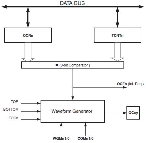
Figure 2: ATmega8 Timer2 (8bit)
Timer/Counter2 is the simplest PWM device on the ATmega8.
Timer/Counter2 is capable of running on 2 modes the Fast PWM mode and the Phase Corrected PWM mode. And each of these modes can be inverted or none-inverted.
Fast PWM mode:
Fast PWM works the same way as the normal counter. The Control Logic receives the signal and increments the TCNT2 register. When a match is detected the OCF0x flag is set and signal is send to the Waveform Generator. The Waveform Generator then changes the state of the OC0x pin (the state is determined by the selected mode). When the TCNT2 register passes the TOP value (0xFF or 255) it simply overflows (or overruns) back to 0, at the same time the OCF2 flag is set. The OCF2 flag can be configured to trigger an interrupt. The OCF2 flag can be cleared by software, but as always is cleared automatically when an interrupt request is triggered.
This mode can be inverted or none-inverted. In none-inverted mode OC2 pin is HIGH(VCC) if TCNT2 is less then OCR2 and LOW(GND) if TCNT2 is greater then or equal to OCR2. In inverted mode the OC2 pin is LOW(GND) if TCNT2 is less then OCR2 and HIGH(VCC) if TCNT2 is greater then or equal to OCR2.
Due to the high frequency of this mode is best used for DAC, fading LEDs, rectification and Power regulation.
The Frequency of the fast PWM can be calculated by the following equation.
PWM_fequency = clock_speed / (Prescaller_value * 256)
Phase Corrected PWM:
The phase corrected mode is a bit strange, it counts up until it hits the TOP value (0xFF or 255) then starts to count down until it hits the BOTTOM (0). The Control Logic receives the signal and increments the TCNT2 register. When a match is detected the OCF2 flag is set and signal is send to the Waveform Generator. The Waveform Generator then changes the state of the OC2 pin (the state is determined by the selected mode). When the TCNT2 register hits the TOP value (0xFF) the OCF2 flag is set. The OCF2 flag can be configured to trigger an interrupt. The OCF2 flag can be cleared by software, but as always is cleared automatically when an interrupt request is triggered.
This mode can be inverted or none-inverted. In none-inverting mode, the OC2 pin is LOW(GND) on the Compare Match between TCNT2 and OCR2 while up-counting, and HIGH(VCC) on the Compare Match while down-counting. In inverting mode, the OC2 pin is HIGH(VCC) on the Compare Match between TCNT2 and OCR2 while up-counting, and LOW(GND) on the Compare Match while down-counting.
This mode is recommended for motor control.
The frequency of the Phase Corrected PWM can be calculated by the following equation.
PWM_frequency = clock_speed / ( Prescaller_value * 510 )
| 7 bit | 6 bit | 5 bit | 4 bit | 3 bit | 2 bit | 1 bit | 0 bit | |
|---|---|---|---|---|---|---|---|---|
| TCCR2 | FOC2 | WGM21 | COM21 | COM20 | WGM20 | CS22 | CS21 | CS20 |
Timer/Counter Control Register 2
| CS22 | CS21 | CS20 | DESCRIPTION |
|---|---|---|---|
| 0 | 0 | 0 | Timer/Counter2 Disabled |
| 0 | 0 | 1 | No Prescaling |
| 1 | 0 | 0 | Clock / 8 |
| 0 | 1 | 1 | Clock / 32 |
| 1 | 0 | 0 | Clock / 64 |
| 1 | 0 | 1 | Clock / 128 |
| 1 | 1 | 0 | Clock / 256 |
| 1 | 1 | 1 | Clock / 1024 |
CS bits Settings
| MODE | WGM21 | WGM20 | DESCRIPTION |
|---|---|---|---|
| 0 | 0 | 0 | Normal |
| 1 | 0 | 1 | PWM Phase Corrected |
| 2 | 1 | 0 | CTC |
| 3 | 1 | 1 | Fast PWM |
Waveform Generator Mode bits
| COM21 | COM20 | DESCRIPTION |
|---|---|---|
| 0 | 0 | OC2 disabled |
| 0 | 1 | Reserved |
| 1 | 0 | None-inverted mode (HIGH at bottom, LOW on Match) |
| 1 | 1 | Inverted mode (LOW at bottom, HIGH on Match) |
Applies only to PWM modes
| 7 bit | 6 bit | 5 bit | 4 bit | 3 bit | 2 bit | 1 bit | 0 bit | |
|---|---|---|---|---|---|---|---|---|
| TIMSK | OCIE2 | TOIE2 | TICIE1 | OCIE1A | OCIE1B | TOIE1 | - | TOIE0 |
Timer/Counter Interrupt Mask Register
| 7 bit | 6 bit | 5 bit | 4 bit | 3 bit | 2 bit | 1 bit | 0 bit | |
|---|---|---|---|---|---|---|---|---|
| TIFR | OCF2 | TOV2 | ICF1 | OCF1A | OCF1B | TOV1 | - | TOV0 |
Timer/Counter Interrupt Flag Register
| 7 bit | 6 bit | 5 bit | 4 bit | 3 bit | 2 bit | 1 bit | 0 bit | |
|---|---|---|---|---|---|---|---|---|
| TCNT2 |
Timer/Counter Register (stores the counter value)
| 7 bit | 6 bit | 5 bit | 4 bit | 3 bit | 2 bit | 1 bit | 0 bit | |
|---|---|---|---|---|---|---|---|---|
| OCR2 |
Output Compare Register (stores the compare value)
ATmega8 Code:
    // this code sets up counter2 for an 8kHz Fast PWM wave @ 16Mhz Clock

    #include <avr/io.h>

    int main(void)
    {
        DDRB |= (1 << DDB3);
        // PB3 is now an output

        OCR2 = 128;
        // set PWM for 50% duty cycle

        TCCR2 |= (1 << COM21);
        // set none-inverting mode

        TCCR2 |= (1 << WGM21) | (1 << WGM20);
        // set fast PWM Mode

        TCCR2 |= (1 << CS21);
        // set prescaler to 8 and starts PWM

        while (1)
        {
            // we have a working Fast PWM
        }
    }
TIMER1 (16BIT PWM):
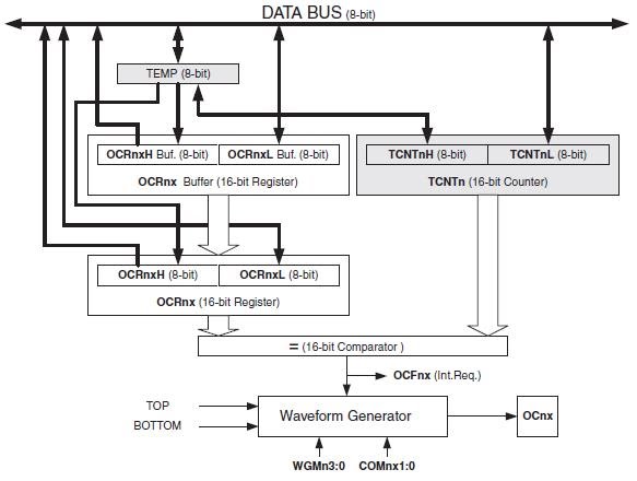
Figure 3: ATmega8 Timer1 (16bit)
Timer/Counter1 is pretty cool because it has 2 outputs, OC1A and OC1B. Since both of these outputs run off the same timer and waveform generators both OC1A and OC1B are synchronized, this make the timer perfect for making tank robots (I love tank robots).
Timer/Counter1 works the same way as Timer/Counter2. The OCR1A/OCR1B are compared to the TCNT1 registers, when a match is detected the OCF1A/OCF1B flag is set and the signal is send to the Waveform Generator. The Waveform Generator then changes the state of the OC1A/OC1B pin (the state is determined by the selected mode). The OCF1A/OCF1B flag can be configured to trigger an interrupt. The OCF1A/OCF1B flag can be cleared by software, but as always is cleared automatically when an interrupt request is triggered. Timer/Counter1 has a separate vector for A and B with A having priority.
Timer/Counter1 is capable of running in 3 modes the Fast PWM mode, the Phase Corrected PWM mode and, Phase and Frequency Corrected mode. Each of these modes can be inverted or none-inverted. Unlike Timer/Counter2 Timer/Counter1 has several options for controlling the max value of the PWM (see chart below). Some modes have a fixed TOP such as mode 1 which is fixed at 0x00FF. While others use a TOP value that is stored in the ICR1 or OCR1A register, such as mode 8 to 15.
Fast PWM mode:
Fast PWM on timer/counter1 works just like it does on timer/counter2. It counts until it reaches the top then overflows back to 0. The big difference is that we have several Fast PWM modes with various TOP values. The only thing that we should note is that if you use ICR1 or OCR1A for the TOP value the MINIMUM valid value is 3 (0x0003).
Due to the high frequency of this mode is best used for DAC, fading LEDs, rectification and Power regulation.
The Frequency of the fast PWM can be calculated by the following equation.
PWM_fequency = clock_speed / [Prescaller_value * (1 + TOP_Value) ]
Phase Corrected PWM mode:
The phase corrected mode on timer/counter1 works just like the phase corrected mode on timer/counter2 (see above for details). Once again the big difference is that we can use the value of ICR1 or OCR1A as the TOP value
This mode can be inverted or none-inverted. In none-inverting mode, the OC1 pin is LOW(GND) on the Compare Match between TCNT1 and OCR1A/OCR1B while up-counting, and HIGH(VCC) on the Compare Match while down-counting. In inverting mode, the OC2 pin is HIGH(VCC) on the Compare Match between TCNT1 and OCR1A/OCR1B while up-counting, and LOW(GND) on the Compare Match while down-counting.
This mode is recommended for motor control.
The frequency of the Phase Corrected PWM can be calculated by the following equation.
PWM_frequency = clock_speed / (2 * Prescaller_value * TOP_value )
Phase and Frequency Corrected PWM mode:
Phase Corrected and Phase and Frequency Corrected PWM modes function the same way if we are not planning on changing our TOP value once the PWM mode is started. The only difference that I could see on the data sheet is that the Phase and Frequency Corrected mode updates its TOP value when it hits Bottom while the Phase Corrected mode updates its TOP value when it hits the TOP.
If anyone knows anything more (or if I'm wrong) about these 2 modes please let me know.
This mode is recommended for motor control.
The frequency of the Phase and Frequency Corrected PWM can be calculated by the following equation.
PWM_frequency = clock_speed / (2 * Prescaller_value * TOP_value )
| 7 bit | 6 bit | 5 bit | 4 bit | 3 bit | 2 bit | 1 bit | 0 bit | |
|---|---|---|---|---|---|---|---|---|
| TCCR1A | COM1A1 | COM1A0 | COM1B1 | COM1B0 | FOC1A | FOC1B | WGM11 | WGM10 |
Timer/Counter Control Register 1 A
| COM1A1 COM1B1 |
COM1A0 COM1B0 |
DESCRIPTION |
|---|---|---|
| 0 | 0 | Normal port operation, OC1A/OC1B disconnected. |
| 0 | 1 | Mode 9, 14, 15 only: Enable OCR1A only (OC1B disconnected) |
| 1 | 0 | None-inverted mode (HIGH at bottom, LOW on Match) |
| 1 | 1 | Inverted mode (LOW at bottom, HIGH on Match) |
Applies only to PWM modes
| 7 bit | 6 bit | 5 bit | 4 bit | 3 bit | 2 bit | 1 bit | 0 bit | |
|---|---|---|---|---|---|---|---|---|
| TCCR1B | ICNC1 | ICES1 | - | WGM13 | WGM12 | CS12 | CS11 | CS10 |
Timer/Counter Control Register 1 B
| CS12 | CS11 | CS10 | DESCRIPTION |
|---|---|---|---|
| 0 | 0 | 0 | Timer/Counter1 Disabled |
| 0 | 0 | 1 | No Prescaling |
| 1 | 0 | 0 | Clock / 8 |
| 0 | 1 | 1 | Clock / 64 |
| 1 | 0 | 0 | Clock / 256 |
| 1 | 0 | 1 | Clock / 1024 |
| 1 | 1 | 0 | External clock source on T1 pin, Clock on Falling edge |
| 1 | 1 | 1 | External clock source on T1 pin, Clock on rising edge |
CS bits Settings
| MODE | WGM13 | WGM12 | WGM11 | WGM10 | DESCRIPTION | TOP |
|---|---|---|---|---|---|---|
| 0 | 0 | 0 | 0 | 0 | Normal | 0xFFFF |
| 1 | 0 | 0 | 0 | 1 | PWM, Phase Corrected, 8bit | 0x00FF |
| 2 | 0 | 0 | 1 | 0 | PWM, Phase Corrected, 9bit | 0x01FF |
| 3 | 0 | 0 | 1 | 1 | PWM, Phase Corrected, 10bit | 0x03FF |
| 5 | 0 | 1 | 0 | 1 | Fast PWM, 8bit | 0x00FF |
| 6 | 0 | 1 | 1 | 0 | Fast PWM, 9bit | 0x01FF |
| 7 | 0 | 1 | 1 | 1 | Fast PWM, 10bit | 0x03FF |
| 8 | 1 | 0 | 0 | 0 | PWM, Phase and Frequency Corrected | ICR1 |
| 9 | 1 | 0 | 0 | 1 | PWM, Phase and Frequency Corrected | OCR1A |
| 10 | 1 | 0 | 1 | 0 | PWM, Phase Correct | ICR1 |
| 11 | 1 | 0 | 1 | 1 | PWM, Phase Correct | OCR1A |
| 14 | 1 | 1 | 1 | 0 | Fast PWM | ICR1 |
| 15 | 1 | 1 | 1 | 1 | Fast PWM | OCR1A |
Waveform Generator Mode bits (Abbreviated)
| 7 bit | 6 bit | 5 bit | 4 bit | 3 bit | 2 bit | 1 bit | 0 bit | |
|---|---|---|---|---|---|---|---|---|
| TIMSK | OCIE2 | TOIE2 | TICIE1 | OCIE1A | OCIE1B | TOIE1 | - | TOIE0 |
Timer/Counter Interrupt Mask Register
| 7 bit | 6 bit | 5 bit | 4 bit | 3 bit | 2 bit | 1 bit | 0 bit | |
|---|---|---|---|---|---|---|---|---|
| TIFR | OCF2 | TOV2 | ICF1 | OCF1A | OCF1B | TOV1 | - | TOV0 |
Timer/Counter Interrupt Flag Register
| 7 bit | 6 bit | 5 bit | 4 bit | 3 bit | 2 bit | 1 bit | 0 bit | |
|---|---|---|---|---|---|---|---|---|
| TCNT1H | ||||||||
| TCNT1L |
Timer/Counter Register (stores the counter value, 16 bit)
| 7 bit | 6 bit | 5 bit | 4 bit | 3 bit | 2 bit | 1 bit | 0 bit | |
|---|---|---|---|---|---|---|---|---|
| OCR1AH | ||||||||
| OCR1AL |
Output Compare Register A (stores the compare value, 16 bit)
| 7 bit | 6 bit | 5 bit | 4 bit | 3 bit | 2 bit | 1 bit | 0 bit | |
|---|---|---|---|---|---|---|---|---|
| OCR1BH | ||||||||
| OCR1BL |
Output Compare Register B (stores the compare value, 16 bit)
ATmega8 Code:
    // this code sets up counter1 for an 4kHz, 10bit, Phase Corrected PWM
    // @ 16Mhz Clock

    #include <avr/io.h>

    int main(void)
    {
        DDRB |= (1 << DDB1);
        // PB1 is now an output

        OCR1A = 0x01FF;
        // set PWM for 50% duty cycle @ 10bit

        TCCR1A |= (1 << COM1A1);
        // set none-inverting mode

        TCCR1A |= (1 << WGM11) | (1 << WGM10);
        // set 10bit phase corrected PWM Mode

        TCCR1B |= (1 << CS11);
        // set prescaler to 8 and starts PWM

        while (1)
        {
            // we have a working Fast PWM
        }
    }
OTHER RESOURCES:
Believe it or not this tutorial almost killed me. I don't know why, maybe its because I'm so close to releasing the site to the public.
Cheers
Q